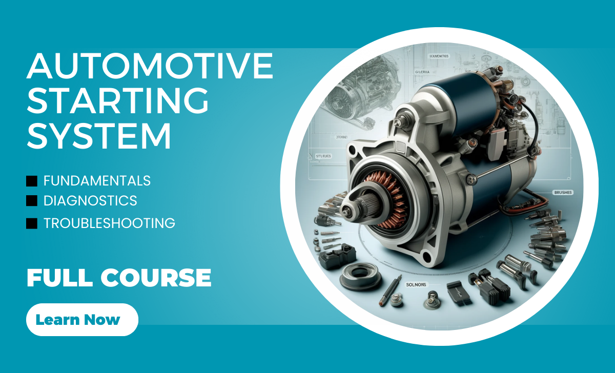
Automotive Starting System Course
Learning Outcomes for the Course
- Understand the Automotive Starting System
- Identify Key Components and Their Functions
- Analyze Automotive Electrical Schematics
- Label and Evaluate Voltage Areas
- Identify Components in Electrical Schematics
- Diagnose Faults in the Starter System
- Apply Case Studies to Real-World Scenarios
- Perform Schematic-Based Fault Diagnosis
- Build Practical Skills in Automotive Diagnostics
- Demonstrate Knowledge Through Assessment
Course Modules
- Module 1: Introduction to the Automotive Starting System
- Module 2: Understanding the Starter Motor
- Module 3: Electrical Schematics and Voltage Areas
- Module 4: Identifying and Analyzing System Components
- Module 5: Diagnosing Electrical Faults
Module 1: Introduction to the Automotive Starting System
The automotive starting system is what gets your car’s engine running. It’s like the spark that wakes up the car and gets everything moving
Lesson 1: Purpose of the Starting System
The starting system is designed to kickstart the engine and get it running. Without this system, the engine wouldn’t be able to begin the combustion process on its own. It ensures the car comes to life whenever you turn the key or press the start button.
Definition and Function of the Starting System
- Definition: The starting system is a combination of electrical and mechanical components that work together to initiate engine operation by cranking the engine.
- Function:
- Power Delivery: It draws power from the battery.
- Engine Cranking: The system cranks the engine to help it start the combustion process.
- Bridge to Engine Operation: Once the engine begins running, the starting system disengages, allowing the engine to operate independently.
How the Starting System Supports Engine Operation
- The system initiates the rotation of the engine’s crankshaft, which is essential to begin the fuel-air compression process in the engine cylinders.
- By creating this initial motion, the starting system allows the engine to produce its own power and sustain operation through internal combustion.
Examples of Starting Systems in Different Vehicles
Traditional Gasoline Cars:
- Use a key or button to activate an electric starter motor powered by the battery.
- Common in everyday cars like Toyota Corolla or Ford F-150.
Diesel Vehicles:
- Diesel engines require more cranking power due to higher compression ratios.
- The starter system in trucks like the Ford Super Duty or large equipment like Caterpillar bulldozers includes heavy-duty components.
Hybrid Cars:
- Have both a conventional starter motor and an electric motor that assists in starting the engine.
- Examples: Toyota Prius or Honda Insight.
Electric Vehicles (EVs):
- Do not have a traditional starting system since the motor starts instantly when power is supplied.
- Example: Tesla Model 3 or Nissan Leaf.
Lesson 2: Components of the Starting System
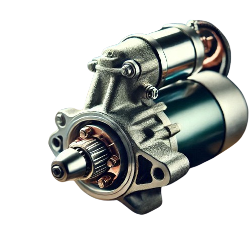
Starter motor
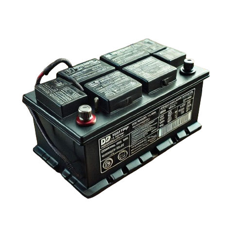
Battery
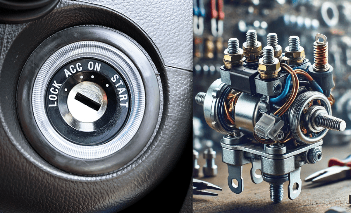
Solenoid and ignition switch
Module 2: Understanding the Starter Motor
Lesson 3: Main Parts of the Starter Motor
The starter motor is a crucial part of the starting system, responsible for turning the engine’s crankshaft to initiate operation. It converts electrical energy from the battery into mechanical energy to get the engine running. Let’s break down its main parts and how they work together.
Main Parts of the Starter Motor
1. Armature
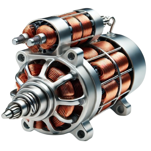
- What It Is: A rotating coil of wire or winding inside the starter motor.
- Function: The armature spins when current flows through it, creating the mechanical energy needed to turn the engine.
- Key Role: Acts as the primary mover in the system.
2. Brushes
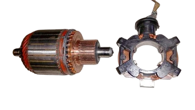
- What They Are: Small carbon or metal pieces that maintain electrical contact with the commutator.
- Function: Transfer electrical current from the stationary parts of the motor to the rotating armature.
- Key Role: Ensure continuous current flow during motor operation.
3. Field Coils
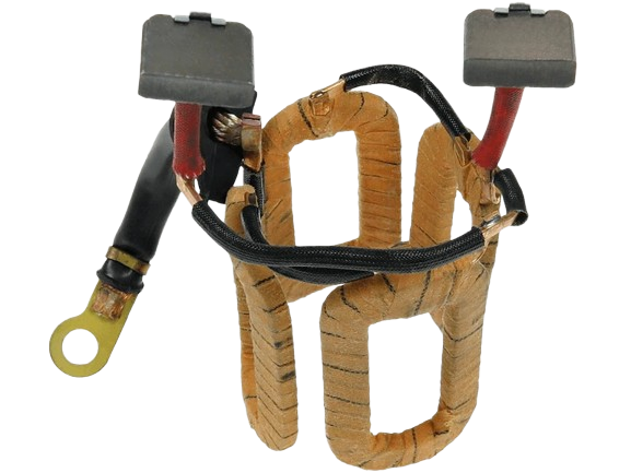
- What They Are: Coils of wire mounted inside the starter motor housing.
- Function: Generate a magnetic field when electricity passes through them.
- Key Role: Work with the armature to create the rotational force needed for the engine.
4. Commutator
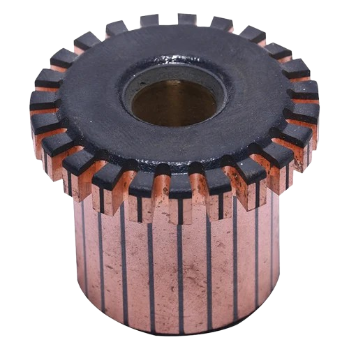
- What It Is: A segmented cylindrical piece attached to the armature.
- Function: Acts as a switch to reverse the direction of current flow in the armature windings, ensuring smooth rotation.
- Key Role: Keeps the armature spinning in one consistent direction.
5. Drive Mechanism
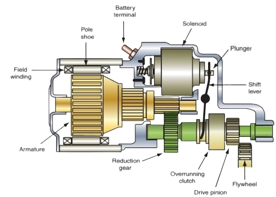
- What It Is: A gear system that connects the starter motor to the engine’s flywheel.
- Function: Transfers the rotational force from the armature to the engine’s crankshaft.
- Key Role: Temporarily engages the flywheel to crank the engine, then disengages once the engine starts.
- Example: Bendix Drive is a common type of drive mechanism used in starter motors.
How These Parts Work Together
- When the ignition switch is activated, power from the battery flows to the starter motor.
- The field coils create a magnetic field, and the armature begins to rotate.
- The brushes and commutator ensure smooth and continuous current flow for consistent armature rotation.
- The drive mechanism engages with the engine’s flywheel, transferring the armature’s rotation to crank the engine.
- Once the engine starts, the drive mechanism disengages, and the starter motor stops.
Visual Aids and Diagrams
Visual aids can make understanding the parts of a starter motor much easier. Here’s what a diagram might include:
1.A labeled diagram of the starter motor showing:
- Armature
- Brushes
- Field Coils
- Commutator
- Drive Mechanism
Lesson 4: Functions and Interactions of Components
The starter motor and its components work together seamlessly to convert electrical energy into mechanical energy, which cranks the engine and starts your vehicle. Understanding how these components interact gives insight into the system’s operation and helps identify common failure points.
How the Parts Work Together to Start the Engine
Ignition Activated:
- When you turn the key or press the start button, the ignition switch sends an electrical signal to the starter motor via the solenoid.
- The battery provides the electrical power needed for the process.
Magnetic Field Created:
- The field coils inside the starter motor create a magnetic field when current flows through them.
- This magnetic field interacts with the armature.
Armature Rotation:
- The magnetic force causes the armature to spin rapidly.
- The commutator ensures the armature receives a consistent and alternating current to maintain smooth rotation.
Engaging the Engine:
- The spinning armature connects to the drive mechanism, which includes a small gear that engages with the engine’s flywheel.
- The drive mechanism turns the flywheel, which starts the engine’s crankshaft rotation.
Disengagement:
- Once the engine starts running, the drive mechanism automatically disengages from the flywheel, preventing damage to the starter motor.
Common Failure Points
- Battery Issues:
- Problem: Weak or dead battery leads to insufficient power to the starter motor.
- Symptom: Clicking sounds or no response when trying to start the car.
- Worn Brushes:
- Problem: Brushes that transfer electricity to the armature may wear out over time, causing poor contact.
- Symptom: Inconsistent or no rotation of the starter motor.
- Faulty Solenoid:
- Problem: The solenoid might fail to engage the starter motor or transfer electrical current.
- Symptom: The starter motor doesn’t activate, or the flywheel doesn’t engage.
- Damaged Drive Mechanism:
- Problem: Wear or damage to the drive gear can prevent it from properly engaging the flywheel.
- Symptom: Grinding noise when starting the engine.
- Burnt Armature or Field Coils:
- Problem: Overheating or electrical shorts can damage these components.
- Symptom: The starter motor may turn slowly or fail entirely.
- Commutator Wear:
- Problem: Over time, the commutator may develop grooves or lose conductivity, disrupting the armature’s rotation.
- Symptom: Starter motor struggles to rotate or works intermittently.
- Battery Issues:
Module 3: Electrical Schematics and Voltage Areas
Lesson 5: Introduction to Automotive Electrical Schematics
Automotive electrical schematics are like maps that show how the electrical systems in a vehicle are connected. Understanding these diagrams helps technicians and enthusiasts troubleshoot problems or make modifications. This lesson will introduce you to the basics of schematics, including symbols, labels, and common conventions.
1. Symbols in Automotive Schematics
Symbols are used in schematics to represent electrical components. Learning these symbols is essential for reading and interpreting diagrams. Here are some common ones:
- Battery: Represented as a set of parallel lines, one longer (positive) and one shorter (negative).
- Ground: A series of descending lines or a triangle symbol pointing downward.
- Switch: Two dots connected by a line, showing open or closed states.
- Relay: A rectangle with lines representing the coil and contacts.
- Resistor: A zigzag or rectangle, depending on the diagram style.
- Motor: A circle with the letter “M” inside or a fan-shaped icon.
- Diode: A triangle pointing to a line, indicating current direction.
2. Labels and Interpretation
Labels provide additional information about the components and wiring:
- Wire Colors: Often abbreviated, such as “BLK” for black or “RED” for red.
- Wire Gauge: Indicates the thickness of the wire, often critical for determining current-carrying capacity.
- Connector Numbers: Show which wire connects to which pin on a plug or terminal block.
- Voltage and Current Ratings: These appear near components to show operating limits.
3. Common Conventions in Automotive Diagrams
Automotive schematics follow specific conventions to maintain consistency and clarity. Here are the most common:
- Circuit Orientation:
- Power (positive) is usually shown at the top of the diagram.
- Ground (negative) is at the bottom.
- Line Types:
- Solid Lines: Represent physical wires.
- Dashed Lines: Indicate optional circuits or signal paths.
- Numbering Systems:
- Wires and connectors are numbered for easy tracing during troubleshooting.
- Modules and Subsystems:
- Each subsystem (e.g., headlights, ignition, or starter motor) is typically grouped together to simplify understanding.
- Connector Views:
- Diagrams often include views of connectors as if you’re looking at them head-on.
- Component Interaction:
- Arrows or labels might indicate relationships between components, such as signals sent from one module to another.
Lesson 6: Labeling Voltage Areas
Labeling voltage areas in automotive schematics helps identify where power flows and assists in troubleshooting electrical issues. By using color-coded labels, you can easily see voltage levels across different parts of a circuit, making it clearer and more organized. In this lesson, we’ll learn how to highlight expected voltage areas and practice labeling through interactive exercises.
1. Steps to Label Voltage Areas
- Identify the Power Source: Start at the battery or primary power supply and trace the positive and ground paths.
- Follow Circuit Flow: Use the schematic to see where voltage is distributed, including through relays, switches, or resistors.
- Mark Key Points: Highlight voltage levels at critical components like the ignition switch, starter relay, and sensors.
- Label Using Colors: Apply the appropriate color to each voltage area for easy identification.
2. Hands-On Activity: Interactive Schematic Labeling
For this activity, let’s practice labeling voltage areas on a sample automotive schematic. Follow these steps:
Step 1: Analyze the Circuit
Examine a basic schematic for a starter system, which includes:
- Battery
- Ignition switch
- Starter relay
- Starter motor
Step 2: Highlight Voltage Areas
Using colors:
- Mark the battery positive (+12V) path in red.
- Highlight the starter motor connection in blue, showing it is powered when the relay is activated.
- Mark the ground connections in green.
- Identify any control circuits (e.g., ECU or sensor inputs) in yellow.
Step 3: Label Components
Label the expected voltage at:
- The ignition switch (12V when ON).
- The starter relay (12V on activation side).
- The starter motor (12V when engaged).
5. Common Mistakes and Troubleshooting
- Mislabeling Grounds: Ensure all return paths to the battery negative or chassis ground are labeled as 0V (green).
- Forgetting Switched Circuits: Mark paths that depend on a switch or relay state distinctly (blue).
- Ignoring Voltage Drops: Some circuits may show slightly lower voltages due to resistance note these variations.
Module 4: Identifying and Analyzing System Components
Lesson 7: Identifying Components on Schematics
Automotive schematics can seem overwhelming at first, but with practice, identifying key components becomes second nature. This lesson focuses on locating essential components such as the starter motor, solenoid, battery, and ignition switch in a schematic, with practical tips to make the process quick and efficient.
1. Key Components and Their Symbols
Here’s a breakdown of the components we’ll focus on and their common schematic symbols:
- Starter Motor:
- Symbol: Typically a circle with an “M” inside or a motor symbol with a gear.
- Location: Connected to the engine’s flywheel through the starter relay or solenoid.
- Solenoid:
- Symbol: A rectangle representing the coil with switch contacts nearby.
- Location: Between the battery and starter motor, acting as a bridge to transfer power.
- Battery:
- Symbol: Parallel lines, one longer (positive) and one shorter (negative).
- Location: Often at the top or side of the diagram as the power source.
- Ignition Switch:
- Symbol: A switch icon with multiple positions labeled, such as “OFF,” “ACC,” and “START.”
- Location: Between the battery and solenoid or relay.
2. Practical Tips for Quick Identification
- Start with the Battery:
- Look for the source of power (positive and negative terminals).
- Trace wires leaving the positive terminal to identify connected components.
- Follow the Power Flow:
- From the battery, trace the schematic to find the ignition switch. This will often lead to the solenoid or relay.
- Locate the Starter Motor:
- Follow the solenoid or relay output to find the starter motor. It will usually connect directly to the engine or flywheel.
- Look for Labels:
- Schematics often label components with abbreviations:
- BAT for battery
- IGN for ignition switch
- SOL or RLY for solenoid/relay
- MTR for motor
- Schematics often label components with abbreviations:
- Use Context Clues:
- Components are grouped logically:
- Power sources (battery) are at the top.
- Control elements (ignition switch) are in the middle.
- Loads (starter motor) are at the end.
- Components are grouped logically:
- Check for Grounds:
- Components like the starter motor and solenoid will have connections to ground (negative terminal or chassis).
4. Common Mistakes and How to Avoid Them
- Confusing Symbols:
- Study the standard symbols for automotive components to avoid mix-ups. Keep a reference sheet handy during practice.
- Skipping Connections:
- Carefully trace wires between components to ensure you understand their interactions.
- Overlooking Grounds:
- Remember that every electrical component must complete a circuit through the ground.
- Confusing Symbols:
Module 5: Diagnosing Electrical Faults
Lesson 9: Introduction to the Process of Elimination
The process of elimination is a diagnostic method where you systematically test components or areas of a system to identify faults by ruling out those that are functioning correctly. In automotive diagnostics, it’s highly effective because:
- Many electrical faults share similar symptoms.
- It narrows down the root cause without unnecessary part replacements.
- It saves time and resources.
Why Is It Effective?
- Systematic Approach: Ensures every potential fault is considered without skipping critical components.
- Prevents Guesswork: Replacing parts based on assumptions is costly and inefficient.
- Identifies Hidden Issues: Electrical faults can be subtle, such as weak grounds or intermittent connections.
Step-by-Step Approach
Understand the System:
- Study the schematic to know how the components interact.
- Familiarize yourself with the normal operation of the system.
Confirm the Symptoms:
- Clearly identify what the issue is (e.g., no crank, clicking noise, or no response).
Start with the Basics:
- Check the battery voltage and ensure all connections are secure.
- Verify fuses and relays associated with the system.
Test Each Component:
- Begin with the most accessible and likely components, such as the battery or ignition switch.
- Use tools like a multimeter to test for voltage, continuity, and resistance.
Eliminate Functioning Components:
- Rule out components that test correctly.
- Continue narrowing down until the faulty part is identified.
Repair or Replace the Faulty Component:
- Fix the identified issue and retest the system to confirm the repair.
Lesson 10: Diagnosing Starter System Issues
Tools for Diagnosing Starter Systems
- Multimeter: Measures voltage, resistance, and continuity.
- Test Light: Checks for power and ground presence.
- Battery Load Tester: Verifies battery health under load.
- Circuit Diagram: Provides a visual guide to the starter system.
- Jump Wires: Used to bypass components for direct testing.
Case Studies: Diagnosing Common Faults
Case 1: No Crank, No Click
- Symptom: The car does not respond when the ignition switch is turned.
- Steps:
- Check the battery voltage (should be 12.6V or higher).
- Inspect battery connections for corrosion or looseness.
- Test the ignition switch output to the starter solenoid.
- Check for blown fuses or faulty relays.
- Solution: Loose battery terminal.
Case 2: Clicking Sound but No Crank
- Symptom: A clicking sound is heard, but the engine does not turn over.
- Steps:
- Verify battery voltage and load capacity.
- Inspect the solenoid to ensure it’s engaging the starter motor.
- Test the starter motor by bypassing the solenoid.
- Check the ground connection for corrosion or damage.
- Solution: Worn-out starter motor.
Case 3: Slow Cranking
- Symptom: The engine cranks slowly before starting.
- Steps:
- Test the battery under load.
- Check for voltage drops in the starter circuit (battery to starter motor).
- Inspect cables for resistance due to corrosion or damage.
- Test the starter motor’s internal resistance.
- Solution: High resistance in battery cables.
Practical Exercise: Diagnose Faults in a Provided Schematic
Scenario:
You’re provided with a starter system schematic where the engine fails to start. Perform these steps to identify the fault:
- Step 1: Analyze the Schematic
- Identify key components: battery, ignition switch, solenoid, starter motor, and grounds.
- Note expected voltages at various points in the circuit.
- Step 2: Perform Virtual Testing
- Use a multimeter to “test” the battery voltage, ignition switch output, and solenoid activation.
- Step 3: Identify the Fault
- Based on the test results, determine which component is not functioning correctly (e.g., low voltage at the solenoid input).
- Step 4: Propose a Solution
- Recommend the repair or replacement of the faulty component.


